

DEC, the Digital Equipment Corporation, was founded in 1957 by Ken Olson and Harlan Anderson. Initially, the company produced logic modules which were used in control systems and also for teaching. When they started making computers, in 1960, they used the term Programmed Data Processor (PDP) to describe their products, rather than the more usual term computer.
Why?
It was a question of image. By renaming their product, DEC avoided the impression that their machines were necessarily vastly expensive and required specialised buildings and staff to house and run them. Also, by directing their machines at scientists, rather than the business community, DEC were able to reduce their software and support costs to a minimum. Scientists enjoyed playing with the new toys and were happy to spend time developing their own programs. Consequently, DEC's early computers were sold at about one tenth of the cost of machines then currently on the market.
The first machine was the PDP-1, this was followed by the PDP-4, 5,6 7 and then the PDP-8.
For more detailed background information see PDP8 FAQ and List of Models - external link
The PDP8 family of computers was produced by DEC between 1965 and 1990. During this time, the physical form of the machines changed considerably, but all the family had the same instruction set and programs written for one would work on another.
(As with all statements about computers, this last one is, of course, not completely true. There are quirky differences with some of the instructions, but generally speaking it's good enough).
The PDP8 family is intriguing for several reasons:-
The family is infuriating because of:-
The PDP8 family members, in a rough time sequence - some ran concurrently, were as follows:-
TELL ME More about PDP-8 modules busses and backplanes
TELL ME More about PDP-8 Computer. How does it differ from a PC?
PDP-8 The Computer.
Inventory No: 0131
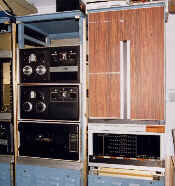
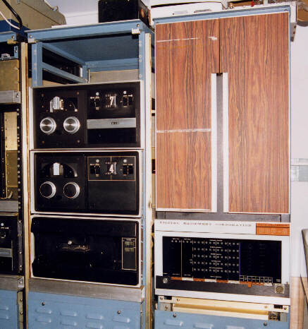
The PDP-8 is the first member of the series, introduced in 1965. It was produced in two variant forms; one rack-mounted with 'rosewood' front panels and the other table-mounted, with smoked, plexiglass panels allowing a tantalising glimpse of the interior. The table mounted version was actually built into its own steel framework (the table!), with the CPU and memory mounted above the table-top and the power supply below. The rack mounted variant could have a 'winged table' to hold a teletype, this fitted just below the programmer's console.
The PDP-8 is largely built from DEC standard logic modules.
TELL ME More about DEC logic modules - their types functions and prices
The illustration shows two cabinets (each one is 69 inches tall by 27 inches wide). The one on the right is the PDP-8, with its 'rosewood' panelling and the programmer's console below. This whole unit will slide forward out of the cabinet. This allows access to the processor (on the right) and the memory (on the left). When fully out, the two halves will then open rather like a book, giving access to the wiring of the backplanes.
The basic PDP-8 consisted of this single cabinet; a processor with 4K words of memory, together with a ASR33 teletype. The teletype comprised a keyboard, a print unit, a paper tape reader and a paper tape punch. All these operated at 10 characters per second. The basic PDP-8 was programmed from paper tape read in from a teletype.
The cabinet on the left in the illustration holds two DECtape drives and a high-speed paper tape reader. These are not part of the basic machine. The basic PDP-8 could be extended, but extra peripheral devices required more cabinets.
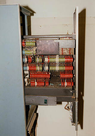
PDP-8 The Processor Side
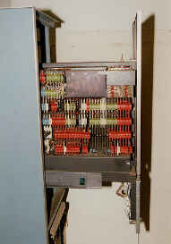
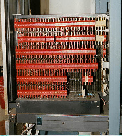
Here the unit has pulled forward out of its cabinet and we are looking at the right hand side (the processor). The edge of the blue cabinet can be seen on the right and the aluminium trim round the rose wood panel on the left.
This machine is almost completely populated, it only lacks the a/d converter, located in the gap, bottom, right of centre. At the right of the bottom two rows can be seen the black 92Ω bundled bus cables. Above these are ribbon cables connecting to the memory side and at the top the white wiring connects to the front panel lights and switches.
See processor side for a colourful diagram of a fully populated machine. There are six rows of cards from PA, at the top, to PF, at the bottom. Each row can accommodate 36 modules, which are numbered from 1, at the back, up to 36, at the front.
PDP-8 The Memory Side
Looking at the memory side. The black box in the centre of the top holds the core memory, 4K 12 bit words. The module locations are numbered in a similar way to the processor side. There are six rows, labelled MA at the top to MF at the bottom. The individual module positions are numbered 1, at the front to 36 at the back. Positions MA&MB 9-24 are occupied by the core.
See Memory side for a colourful diagram of the memory side.
PDP-8 The Memory Side - Detail
Some modules have been removed and the back plane can be seen. The rightmost module in the second row up (row ME position 16) is (yet) another S111 and the protruding block is the flip-chip module.
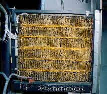
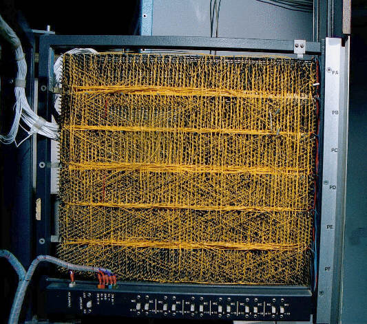
PDP-8 Processor Backplane.
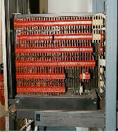
When the unit has been slid completely out of the cabinet, the two halves will hinge apart, opening like a book. This reveals the two wire-wrapped backplanes. Note the complexity. There are 3888 individual connection points on the processor side. Note also that the geometry of the machine is fixed; all were, for instance, prewired for the a/d module.
Also visible at the bottom are a series of white switches. These are for marginal testing. and allow the supply voltage to be varied row by row to identify potentially faulty components.
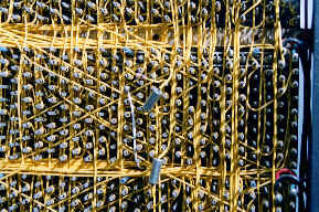
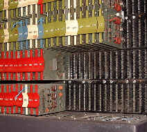
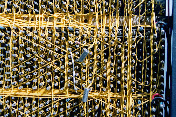
PDP-8 Processor Backplane - Detail
A part of the mass of wire that is the PDP-8 backplane. This gives some idea of the complexity of the wiring, which contributed to a large proportion of the cost of the machine.