

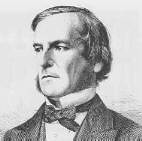
George Boole (1816-1864)
George Boole has played a pivotal rôle in the development of the digital computer, for it was he that developed the now familiar 'Boolean Algebra', now a basis of digital manipulations.
Although he showed exceptional early promise, his education was curtailed because, on the failure of his father's business, George had to support the family. At the age of 16, he began teaching and before he was 20, he opened a small school of his own and he had to combine his teaching duties with his own study of mathematics.
From 1839 onwards, he did publish his work in the Cambridge Mathematical Journal and the Philosophical Transactions of the Royal Society. In 1849, despite his lack of formal university education, he was appointed to the chair of mathematics at Queen's College, Cork.
While there, he published, in 1854 An Investigation into the Laws of Thought, on which are Founded the Mathematical Theories of Logic and Probabilities. With this work there began what came to be known as Boolean Algebra.
Boole died in 1864 and for many years after his death, his work on logic was regarded as being of theoretical interest but lacking in any practical use.
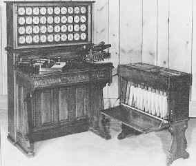
Hollerith Tabulator and sorter (1890)
Herman Hollerith (1860-1929) took the Jacquard punched card concept a stage further when he applied the technique to counting and sorting in the American Census of 1890. His tabulator and sorter illustrated above has a card punch on the left of the desk and a reader on the right.
In operation a card was placed in the reader and the lid closed. A series of spring loaded pins in the lid passed through holes in the card and dipped into small cups of mercury below. This completed circuits which incremented the counters above the desk and also opened one of the 24 flaps on the top of the sorter, according to the category of the card. The card could then be dropped through the open flap to be filed in the correct location in the sorter. When a batch of cards had been processed, the front door of the sorter could be opened, as in the illustration above and the categorised batches of cards removed for further processing.
Hollerith's machine was a great success, operators could each process several thousand cards a day without error and the census was completed in record time. This was the beginning of punched card data processing.
Hollerith set up a manufacturing business, the Tabulating Machine Company and managed it successfully until failing health forced him to withdraw in 1911. Charles Flint, the "Trust King" arranged for the merger of Hollerith's business with two others. One was the Computing Scale Company, which manufactured shop weighing scales. The other was the International Time Recording Company, a maker of clocks which recorded workers hours. Taking one word from the title of each parent company, the result was the Computing Tabulating Recording Company (CTR).
A certain Thomas Watson, who had just been fired from his position as general manager of the National Cash Register Company (NCR), took the position of general manager at CTR; bringing with him the aggressive selling techniques that he had acquired and developed at NCR. By 1914, Watson had become president of a thriving CTR; ten years later he renamed the company "International Business Machines", IBM. The later success of IBM was built upon a solid foundation of punched card business machines. This lead, in turn to punch card reader and punch equipment being adopted for use with early computers. They were available, fast and reliable.
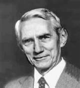
Claude Shannon (1916-2001)
Claude Shannon was born in Gaylord, Michigan, USA and graduated from the University of Michigan with a degree in electrical engineering and mathematics in 1936.
After graduation he worked on Vannevar Bush's differential analyser at the Massachusetts Institute of Technology and at the same time as a research assistant he worked towards a master's degree in electrical engineering.
The complex relay control mechanism of the differential analyser must have had some effect on him, because his masters thesis was entitled A Symbolic Analysis of Relay and Switching Circuits and was on the use of Boolean logic to analyse the behaviour and optimise the design of relay circuits. This thesis has been acclaimed as one of the most significant of the 20th century - it paved the way for the widespread use of binary digital circuitry.
Perhaps Shannon's most important work was A Mathematical Theory of Communication, published in 1948. It set out the groundwork for modern systems of data transmission and, perhaps more familiarly, it popularised the word bit as an abbreviation for bnary�digit. (John Tukey (of FFT fame) was the first to use the word, Claude Shannon was the first to use it in print).
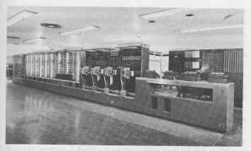
The ASCC or Harvard Mk I
While Howard Hathaway Aiken (1900-1973) was working on his PhD thesis on conduction in thermionic valves (vacuum tubes) in the late 1930s he was harassed by the amount of calculation effort required and he thought that an automatic calculator would be a great help. Aiken was aware of the fragment of Babbage's engine held by Harvard University and had read Passages from the life of a Philosopher, Charles Babbage's autobiography. He was greatly impressed by Babbage's vision.
In 1937 he wrote a memo entitled Proposed Automatic Calculating Machine and he also approached Thomas Watson of IBM for help and funding. A working partnership was arranged and construction started in 1937. The outcome is variously known as the Automatic Sequence Controlled Calculator (ASCC), or The Harvard Mk I. There was some degree of acrimony between the two parties about the allocation of the credit for the design and construction of the machine.
When it was eventually completed in 1943, the machine was 51 feet long, 8 ft high and weighed 5 tons. It contained about 760,000 parts connected by 530 miles of wire. A 4 HP electric motor drove a single shaft running the full width of the machine, this powered the mechanism and synchronised its operation.
The calculator was an electromechanical device and as far as possible IBM standard parts were used in its construction. There were 72 standard IBM rotary registers each holding 23 digits plus sign. There were 60 registers for holding constants, which were entered via a bank of 1440 switches. Four paper tape readers were provided, one for the program, the rest for data. The paper tape used was the same width as an IBM punched card, i.e about 3¼ inches.
The machine was capable of performing its basic operations (add, subtract, read or clear) in one third of a second, multiplication took 6 seconds and log or trig functions could take more than 60 seconds to compute. When operating, the ticking sound of the registers turning was described as being 'like a room full of ladies all knitting'.
It was installed at Harvard University, inaugurated there in August 1944 and ran for 14 years. Three portions survive; one in the lobby of the Science Centre at Harvard, another in the Smithsonian Museum of American History and the third is in IBM's historical collection.
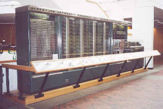
A fragment of the Mk 1 on display in the lobby of the Science
Centre, Harvard
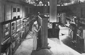
ENIAC at the Moore School - Cpl Irwin Goldstine at a function
table
(U.S. Army photograph)
ENIAC, the Electronic Numerical Integrator And Computer was a giant, about 30 tons in weight. It contained about 18000 valves (tubes), consumed about 174Kw of electricity and filled a room 50ft by 30 ft. ENIAC came into being by a combination of circumstances; the war, long-range gunnery, differential analysers and the interplay of personalities who came together at just the right time.
When the army fires a long-range gun (the range may be several miles), ideally it likes to have an approximate idea of whereabouts the shell is going to land. Several factors affect the range. Apart from the obvious muzzle velocity and elevation and shell form, there are also height above sea level, atmospheric pressure, temperature, wind speed, humidity and local variations in gravitation to allow for. Any particular gun needs a book of tables to give the range for a whole series of different conditions. This is known as a firing table. For a new gun, or type of shell or theatre of war, new firing tables are required.
In America at this time, artillery testing and the preparation of firing tables was carried out at the Army Ordnance Ballistic Research Laboratories of the Aberdeen Proving Ground in Maryland. Because it is impractical to define completely the behaviour of a gun experimentally, by test firing alone, they used a combination of test firing and calculation.
Unfortunately, the trajectory of a shell could not be calculated directly, because the formulae and mathematical treatments available were just not good enough to permit this. They were, however, accurate over a very limited distance. The technique used, therefore, was to divide the trajectory into lots of steps. Knowing the horizontal and vertical components of the velocity of the shell at the start of any particular step, it was possible to calculate a good estimate for the velocity components at the end of the step. These values could then be used as the starting velocities for the next step and the calculation repeated.
In this way the whole trajectory could be calculated, one step at a time. Such repetitive calculations were tedious and very time consuming, but because they were so repetitive, they were ideal candidates for some form of mechanisation.
The immediate threat of war meant that new tables were urgently needed, but each table took months to prepare using a Bush differential analyser and hand cranked calculators. Although the Ballistic Research Laboratory had its own differential analyser, the Moore School of Electrical Engineering at the University of Pennsylvania had a larger and more reliable one. The Army entered into a contract with the Moore School to use this analyser. Lt. (later Captain) Herman Goldstine, a PhD in mathematics from the University of Chicago, was assigned to the university as supervisor of the computation work there.
Also at the Moore School at that time were John William Mauchly (1907-1980) and John Presper Eckert (1919-1995). Mauchly had a long standing interest in meteorology, particularly weather prediction, but the amount of calculation involved prevented much progress. He was interested in computing machinery as a general tool to aid with this work and also, to a certain extent for its own sake.
John Mauchly had been experimenting with electronic pulse handling circuits, such as the bistable circuit (flip-flop) of W�H�Eccles and F�W�Jordan, which used two triode valves and could function either as a pulse counter or a store. Circuits such as this were possible building blocks for an electronic digital computer. He communicated his ideas and enthusiasm to Eckert, reputed to be the best electrical engineer at the Moore School who became an enthusiastic supporter of the project.
Mauchly had heard of a computer project underway at Iowa State College, where John Atanasoff and Clifford Berry were developing the Atanasoff Berry Computer (ABC). In June 1941 Mauchly visited Iowa, and was able to study the ABC in detail. This encouraged him to continue with his efforts to build a computer.
TELL ME More about Atanasoff Berry Computer
In the summer of 1942, Mauchly drafted a proposal outlining the design for a large-scale electronic digital computer, this failed to impress his seniors, nothing was done and the document was lost.
However, Herman Goldstine heard of the proposal and realised how useful a machine such as the one proposed by Mauchly would be for calculating firing tables. He persuaded the army to support the project and Mauchly to rewrite and to resubmit his proposal.
The official proposal was submitted in April 1943 and project PX, the construction of the ENIAC began with J�Presper Eckert as the main project engineer and John Mauchly as consultant. Arthur�W�Burks, Thomas�K�Sharpless and Robert�F�Shaw did much of the detail design work.
The original agreement of June 1943 called for six months 'research and development of an electronic numerical integrator and computer and the delivery of a report thereon'. It allocated just under $62000! In fact, the project actually ran on until 1946 and cost almost $500,000.
ENIAC had a problem, which many experts at the time considered to be so severe that the device could never be made to function. ENIAC contained many, many, MANY more thermionic valves than any previously constructed piece of electronic equipment. Each of these valves contained a heater, (because the cathode of a valve had to run at a dull red heat in order to emit electrons). This heater had an electrical filament and operated in more or less the same way as a modern incandescent light bulb. Like the light bulb, it had a limited life (1000 - 2000 hours). Like a light bulb, it tended to fail when first switched on (POP!).
Now, if a machine contained 18000 valves and each one had a life of between 1000 and 2000 hours, how long would it run for before one failed?
OK, it could not possibly work -- However ....
Eckert got round this problem in two ways. Firstly, he did not switch the heaters off, so that the valves did not suffer that fatal surge of current through a cold (and, therefore, low resistance) heater. Secondly, he under-ran the valves, that is, he operated them below their rated voltages. This combination extended the life of the valves sufficiently for the ENIAC to function.
This is a bit of a simplification and there are other problems with valves as they age. However by adopting a rigorous programme of testing and swapping valves (it took eight hours to test all the valves), engineers succeeded in keeping ENIAC running.
ENIAC consisted of 30 autonomous units, 20 of which were accumulators. ENIAC's accumulators were used both for storage and for arithmetic. Each accumulator could hold a 10 digit DECIMAL number. Numbers were stored in ring counters, arrays of valve flip-flops.
This is a fairly inefficient way of storing numbers and it accounts in part for the large number of valves used in the machine. Note also that ENIAC did not have a central memory or store like that of a modern machine, instead each unit had its operating store, with the major storage location being the accumulators.
Other units included an initiating unit, multiplier, divider/square root unit, a master program unit to control program sequencing and looping and a cycling unit which issued synchronising pulses to all units.
Each unit operated independently although under the overall control of these central clock pulses. A unit was initiated by an input pulse and when it had finished its task, it transmitted the result and a start pulse on to the next unit. In addition to the program units, there were three function tables, banks of switches used for entering and storage of values to be used in a calculation.
ENIAC was amazingly fast by the standards of the day, addition took 200 micro-seconds (µS), multiplication took 2.6 milli-seconds (mS) and a square root took 25 milli-seconds (mS). The extraction of roots is considerably slower that the other operations because of the algorithm used the fact that the square of a number n, is equal to the sum of the first n odd numbers, thus:-
1 + 3 + 5 + 7 + ... + (2n - 1) = n2
Cunningly, this only involved additions and subtractions, but was slow for large numbers.
Programming the device was a matter of cabling the separate units together in the correct combination. This was a lengthy process.
Interestingly, because the various units were capable of operating independently it was possible to operate them in parallel! In practice, this was not usually attempted because of the extra complication and because it was considered good practice to use as few units as possible, as this decreased the chances of failure.
ENIAC was a war-time project, it was needed for the war effort and it had to be completed as soon as possible. It had to use tried and tested techniques and its design was frozen very early in the project so that it would be finished QUICKLY. There simply was no time to experiment, to look for better or more elegant ways of working. It was completed in the amazingly short time of 30 months and it worked.
ENIAC could calculate the trajectory of a shell in 30 seconds. The differential analyser took 15 minutes (when it worked), while a human computer using a calculator took 20 hours. The shell itself took 60 seconds to work out where it was going and to get there, so ENIAC was faster!
While ENIAC worked and worked well, the pace of its development did not allow for any refinement in the design and while the construction was in progress it was realised that ENIAC was going to be difficult to use and in particular, difficult to program. A simpler and more effective design was possible. The solution was to continue with ENIAC and design another machine to incorporate the improvements.
Group discussions at the Moore School defined a better design of architecture leading to Project "PY", the E.D.V.A.C. (Electronic Discrete Variable Automatic Computer). The results of these discussions were summarised by John von Neumann in his First Draft Report of the EDVAC Design. This report outlined the design principles of the modern computer. (See von Neumann, below).
ENIAC was formally inaugurated at the Moore School in February, 1946. During the winter of 1946, it was dismantled and moved to the Aberdeen proving ground, where it was reassembled and started running in August 1947. It was modified at Aberdeen to work on an internally stored but fixed program, and the cabling between the units then could remain fixed. Later, 100 words of magnetic core memory were added.
Finally at 11.45pm, on October 2nd 1955, ENIAC was turned off for the last time. During its life, it had logged a total of 80,223 hours of operation.
The American Army has an excellent website giving details of ENIAC and other early army computers (See: ENIAC external link)
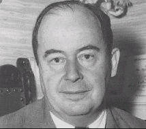
John von Neumann (1903-1957)
John von Neumann was a notably gifted mathematician who came to the USA from Hungary in 1930. By 1933, he was the youngest of the six mathematics professors at the Institute for Advanced Study in Princeton (another being a certain A. Einstein).
During the 1930s, he became interested in the problem of hydrodynamical turbulence. The equations used to analyse this were not amenable to analysis by conventional methods but von Neumann thought they would respond to numerical analysis. Now, numerical analysis is a sort of trial and error procedure that involves tedious and lengthy calculations. He needed a computer.
Von Neumann was the ideal person to be brought into the discussions at the Moore School and his report First Draft Report of the EDVAC Design outlined what was to become the design standard for the modern computer. Indeed, that standard came to be known as "The von Neumann Architecture"
Most importantly, the concept of the stored program. The instructions or orders for the machine were to be stored in memory along with the data. This would eliminate the need to rewire the device for each new task. This might seem obvious to us now, but it was a major step forward.
The great difficulty with computers then (and since) was the storage of numbers, (ENIAC had a smaller store than Babbage had designed for the Analytical Engine). The problem was - what to use? ENIAC's valve flip-flops and ring counters worked for a few numbers but to store instructions and data in the same memory would require thousands of bits of storage. The principle of the stored-program computer was fine but the implementation was not going to be easy.
TELL ME More about memory
During the summer of 1946, the Moore School held a series of 48 lectures entitled Theory and Techniques for the Design of Electronic Digital Computers. These outlined the design principles of the EDVAC (Electronic Discrete Variable Automatic Computer). The Moore School Lectures, as they are now more generally known, were the seed from which grew the earliest projects to build large scale electronic computers.
Ironically, the EDVAC was not the first modern, or stored program, computer to run. The EDVAC project was complex and the computer was not completely operational until 1952.
In the UK at Cambridge, M�V�Wilkes (who had attended part of the Moore School course) produced the EDSAC (Electronic Delay Storage Automatic Computer). This machine, which used about 3,800 valves and mercury delay line storage, was based on a simplified EDVAC design and ran its first program on May 6th 1949, the log book reads:-
"Machine in operation for first time. Printed table of squares (0-99), time for program 2�mins 35�sec. Four tanks of battery 1 in operation"
["Tanks" and "battery" refer to the mercury delay line storage]
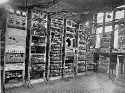
The Manchester Baby (Small Scale Experimental
Machine)
The Small Scale Experimental Machine (SSEM), otherwise known as the "Manchester Baby", was actually the first stored program electronic computer to become operational. The SSEM came into existence because:-
The Manchester Baby was that computer. It was the "child" of FC�(Freddie)�Williams (1911-1977) and Tom Kilburn (1921-2001). Williams and Kilburn had been at the Telecommunications Research Establishment (TRE) at Malvern in the UK during the war, where they were working on radar.
Williams visited America in 1945 and 1946, because he was collaborating on a publication on Electrical Engineering. While there, he saw work on analogue storage using cathode ray tubes (CRT) to remove "ground clutter" in radar displays.
He thought it would be possible to adapt this technique for use as a memory device. Back in England, at TRE he and Tom Kilburn started to investigate the technique, but came to the conclusion that it was better to store the information digitally. Later that year, they had succeeded in storing one bit in a CRT!
In December 1946, Williams was appointed to the Chair of Electro-technics at Manchester and so moved north. He continued to work on the storage project and TRE provided some funding and also seconded Kilburn to it. This secondment was useful because Kilburn was able to draw stores from TRE, a Government Establishment, which had better funding than the university!
By the end of 1947 the storage capacity of a tube had been increased to 2048 bits and Tom Kilburn wrote an important report entitled A storage system for use with Binary Digital Computing Machines . This caused other groups to investigate the technique.
The memory system, now known as the Williams tube worked well under static conditions but it was not known if it would work in "the hurly-burly of computing". Would a bit remain unchanged and readable while all its neighbours were rapidly changing? It needed to be tested under operating conditions in a working computer.
So began the SSEM, the smallest device that could store a program and then execute it. It was built largely from military surplus parts left over at the end of the war. Switches on the control panel, for instance, were channel selectors from Spitfire W/T (radio) sets.
After a lot of initial failures, the first program was run at 11:00 am on 21st June 1948. As Sir Freddie Williams later recalled:-
"A program was inserted and the start switch pressed. Immediately the spots on the display tube entered a mad dance. In early trials it was a dance of death leading to no useful result and what was even worse, without yielding any clues as to what was wrong. But one day it stopped and there, shining brightly in the expected place, was the expected answer. It was a moment to remember. Nothing was ever the same again."
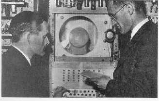
Tom Kilburn & Freddie Williams at the control panel of
the SSEM
This photograph shows the controls of the SSEM. The display CRT is in the centre - there is a large gap round it because initially a surplus radar tube had been used, which was larger. The Spitfire switches are the array of buttons just below the tube.
A replica of the SSEM was built in Manchester and ran a program during the 50th anniversary celebrations on 21 June 1998. For a photograph and a few details:-
TELL ME More about Manchester Baby replica
For more information about the SSEM, its recreation, the early Manchester machines and the people involved see Computer 50 - external link.
For a simulator for the SSEM, see Computer Conservation Society - external link
That is the end of the first part of the story. The computer has been defined and constructed and it works -- nothing will ever be the same again.
From these beginnings until the present day, there have been many changes in technology, allowing machines to become smaller and more powerful and more efficient and smaller and more powerful and more efficient and sm..... and so on and on seemingly without end.
Despite many apparent changes, the underlying principles remain those as outlined for the EDVAC all those years ago. The subsequent story is dominated by miniaturisation but above all by the search for a reliable and cheap method of storing numbers - some things never change.
Some of this story is told through the contents of the old computer hut - (Home) - have a look.