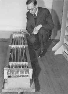
M. V. Wilkes with Mercury delay storage lines from EDSAC
© Copyright Computer Laboratory,
University of Cambridge
Reproduced by permission.
Reproduced by permission.
It is not easy to make a device that will store a lot of numbers. Just about every physical property of matter has been investigated at some time for use as a store. Most were eventually abandoned.
The second world war was a great spur to developments in many fields, one of note being radar. Radar required high power pulses of energy and a lot of research was carried out on circuits to handle pulses rather than the nice gently varying radio waveforms of previous years. Computers also use pulse waveforms and many of the circuit designs were borrowed from radar.
From radar also came some of the storage techniques. The early radar systems were plagued by many spurious signals from reflections off the surrounding terrain which obscured the target. Much research went into various ways of removing this so-called "ground clutter".
One of the more successful ideas was to store the string of reflected signals received after a pulse had been transmitted and then combine it with the signals received from the next pulse. If the stored signals were inverted and the intensities were adjusted correctly, then when combined with the next signals, all the reflections from stationary objects would cancel out and only reflections from objects whose position had changed would remain.
Ok, this sounds easy (?) But how to store the string of pulses?
One early method of storage relied on the fact that sound travels more slowly than an electrical signal.
If a series of pulses of sound are fired into one end of a column of liquid contained in a steel tube, then the pulses will arrive at the other end of the column in sequence after a small delay. The amount of delay depends upon the length of the tube.
Such a device was capable of storing the reflections from a single radar pulse and emitting the stored pulses in synchronisation with the reception of the next set of echoes.
This works fine for a fraction of a millisecond, but a computer needs a store that will hold numbers for a long time. How can we do this?
With hindsight it it obvious, but it wasn't at the time. If a string of pulses can be stored for a fraction of a second, they can be stored for ever. The trick is to take the pulses as they come out of one end of the tube and stuff them back in at the other. In this way, they will keep circulating for all eternity.
As you might imagine, there a a few technical difficulties with this, but that is the principle. In practice, a column of mercury was contained in a steel tube which had quartz crystals mounted at each end. Electrical pulses (modulated by an ultrasonic carrier wave) were applied to the transmitter crystal and the resultant pulses were detected at the receiving end, amplified, reshaped and fed back to the input. The electronics were complicated somewhat by the need to read from and write to the pulse stream, but this is the basis of the "Mercury Delay Storage Line" which was used extensively in early computers.
In the UK, the mercury tubes were generally known as "tanks" to avoid confusion with vacuum tubes. Several tanks would make a "battery".
It is important to realise that the delay line was a serial device. Once a pulse had entered the tube there was no way to get at it until it emerged at the other end. This is more or less acceptable for data, but a bit tedious for storing programs. Programming techniques were evolved which avoided having to wait for the next instruction to emerge from its tube. These meant that the address for the next instruction had to be included in the current instruction word. This allowed the instructions of a sequentially executing program to be located at optimal (but not necessarily sequential) locations in memory, so that an instruction would appear at the end of a tube just when it was needed.
Another storage method that was inherited from radar research was the cathode ray store. This was developed in various forms, one variant being known as the Williams Tube, (or, more fairly, as the Williams-Kilburn Tube). This relies on the fact that when the beam of electrons inside a cathode ray tube (CRT) hits the screen, secondary electrons are emitted from the area of impact. In the normal operation of the CRT, as a display device, this effect is ignored.
When using a CRT tube as a memory device the operating voltages of the tube are adjusted to ensure maximum secondary emission - more electrons are emitted from the impact spot than are arriving in the primary electron beam and a small positive charge builds up in the area of the spot. Now, if a metal plate is fixed over the front of the tube, the sandwiched arrangement of charged spot, glass insulator and metal plate behaves like a capacitor. Changes in the charge on the inside of the tube will appear as small changes of voltage on the external collector plate. This is the essence of the Williams tube storage device.
           AB    CD    EF
    -------++----++----++-  etc.
Suppose that there are adjacent pairs of spots on a scan line AB, CD, EF etc. Suppose also that the intensity (brightness) of the beam can be modulated (Z-modulation), ie the beam can be turned on or off. Now if the beam is set to bombard point A, secondary electrons will be emitted from A and A will become positively charged. Because of the capacity between the charged spot and the external collector plate, a small positive pulse will appear on the plate. If the beam bombards A a second time, there is no effect because A is already positive and no further change occurs. So bombarding an uncharged spot produces a pulse at the collector, bombarding a charged spot does not.
Now, having charged up spot A, suppose we aim the beam at B, immediately next to A and turn the beam on. Secondary electrons are emitted from B, but because of the positive charge on A they are attracted there and annihilate the charge on A. If A is bombarded again, a pulse will appear on the collector. By bombarding A we can tell if B has been bombarded recently or not - we can tell the state of B without examining it directly.
Left undisturbed, the charges on A and B would soon dissipate and so they have to be refreshed periodically. This can now be done in the following way. The beam scans along the line and bombards A. If a pulse appears at the collector, it indicates that there was no charge at A. A's charge had been neutralised on the last pass because B had also been bombarded. To maintain the state of A and B, we must now bombard B again to refresh its charge and to neutralise the charge on A that we have just created.
If, on the other hand, no pulse appears at the collector when A is bombarded, this indicates that A is charged and hence B was not bombarded on the last pass of the beam. To maintain this state of A and B, the beam must be turned off and pass on to C without bombarding B.
Thus, the state of any particular pair of spots can be read or altered at will and, if it is refreshed periodically, the system will hold its state indefinitely. The pairs of points AB, CD etc are sufficiently far apart so the bombardment of one member of a pair has no effect on adjacent pairs.
Using pairs of spots in this way was known as the dot-dash system and was the first method used by Williams and Kilburn. It was, however, affected by local variations in the quality of the CRT screen and was replaced by the focus-defocus method where A was the focussed spot and B became the area surrounding A which was bathed in the electron beam when it was defocussed (blurred). This system was rather more tolerant of faults in the screen.
The CRT store was badly affected by electrical interference so, for instance, a passing motor-cycle, (which in those days did not have suppressed ignition systems) could rewrite the whole store. Because of this, the memory tube was always heavily shielded. A second tube connected in parallel was used as the display device.
Note that the CRT store was a random access device, any location could be addressed and read directly. It was thus much faster and more convenient to use than acoustic delay line memory. The CRT store was widely used in early machines, particularly where performance was important.
Magnetic core memory was the invention of JayĀWĀForrester and was developed with the assistance of a graduate student - Kenneth Olsen. The development of core memory was a spin off from the Whirlwind project. Whirlwind started out in 1944 as a project to build an aircraft stability and control analyser (ASCA), a type of flight simulator intended to simulate the effect of engineering changes on aircraft behaviour. The initial intention was to use analogue computers as the control elements.
However ...
Things got a little out of hand.
Early on in the project Forrester met with Von Neumann and Eckert and was persuaded to develop digital computer control rather than analogue. Forrester now set out to produce a machine that would be fast enough to operate in a real-time control environment. There was much military interest in this, the cold war was beginning, Russia had developed and tested an atomic bomb and possessed bombers capable of carrying an atomic weapon over the North Pole to Canada and the USA. There was seen to be a need to develop systems capable of tracking such bombers and consequently, the project was not short of sponsors or funds. The Whirlwind project eventually led to the development of the SAGE (Semi Automatic Ground Environment) tracking system, whose computers weighed 250 tons and consumed 1000000 Watts of power each - but that is another story.
In the middle of all this, Forrester had the problem of developing fast and reliable memory. Delay lines were far to slow to be of any use and initially Forrester tried using various forms of CRT storage. He had some degree of success with these, but the tubes he was using were very expensive and had a very short life. Something else was needed.
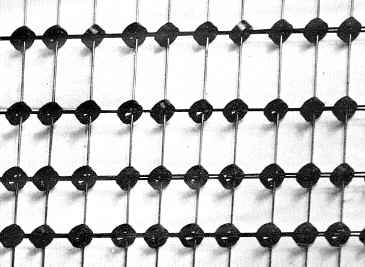
Forrester hit upon the idea of using magnetic storage using an array of ferrite rings strung on the intersections of a grid of wires.
Ferrite has the property that, if is exposed to a sufficiently strong external magnetic field, it will become fully magnetised and it will remain magnetised if the external magnetic field is then removed. Also, it can be magnetised in one of two states (NS or SN) and can be made to flip quickly from one state to the opposite very quickly.
(Remember also that when an electric current passes down a wire, a magnetic field is generated around the wire.The direction of the field depends on the direction of the current.)
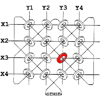
The diagram illustrates an array of rings threaded on a grid of wires, X1 to X4 and Y1 to Y4. If a sufficiently large current is passed along the wire X3, then a magnetic field is generated around the wire and all the cores threaded on the wire in the X3 row will become magnetised. They will remain magnetised when the current is switched off.
Similarly, if a large current is passed along the wire Y3, all the Y3 cores will become magnetised.
If a small current is passed along the wire X3, the field produced is not sufficient to have any effect on the cores. For a given arrangement, there is a particular current which is just sufficient to magnetise the cores.
Now, here comes the clever bit. If a current equal to half this magnetising current is passed along X3 and another half current is passed along Y3, then only the red core at the intersection will receive the full magnetic field. The red core will be magnetised but all the other cores will be unaffected.
If the direction of the currents in X3 and Y3 is now reversed, then the direction of magnetisation of the red core will be reversed, but again, no other cores will be affected.
So far, we have been able to select a particular core and set it into one of two possible states, equivalent to "0" and "1". It doesn't matter which direction of magnetisation we chose to represent a "1" but we do need to be able to detect which of the two possible states a particular core is in. How can we do this?
The diagram shows a third wire (the sense wire) threaded through all cores. Now, when the core changes its magnetic state, the magnetic field inside the ring suddenly flips direction. This moving magnetic field generates a small electrical current in the sense wire, which can be amplified and detected.
So, if we write a "1" to a particular core and this core is in the "0" state, the the field will flip and a pulse will be detected in the sensing wire. On the other hand, if the core was in the "1" state, writing a "1" would have no effect and no pulse would appear on the sense winding. In this way, the state of a particular core can be detected.
Note that the act of reading core memory is destructive. In normal use, the value read would have to be stored and then the core would have to be remagnetised in its original state.
Although the action of reading is destructive, once written, core memory will retain its contents indefinitely (or for a very long time). It does not require any power to maintain its contents.
Early machines used magnetic drum for secondary storage. Drums are more straightforward to work with than other conformations. For the same reason, early sound recording devices used cylinders before turning to disks.
The tracks across a drum all behave identically, each track had its own head and the processor could switch between tracks easily. Drums worked particularly well with acoustic delay line storage as the motion of the drum could be synchronised with the stored pulses travelling through the delay lines.
Thirteen years after LeeĀDeĀForest's invention of the triode valve in 1906,WĀHĀEccles and FĀWĀJordan developed a circuit with two triode valves connected in such a way that it had two stable states; if one valve was conducting, the other was off and vice versa. The circuit was known as the bistable, or more commonly in recent times, the "flip-flop". This circuit would remain in one of its stable states until it received an external pulse which would flip it into its alternate state.
The original version of the ENIAC relied entirely on flip-flops for storage (later core storage was added). Other early machines used other methods for main storage, but used valve flip-flops for registers and temporary storage.
With the advent of transistor flip-flops and, in particular, integrated circuit devices, the flip-flop was again sometimes used for the main store.
Thanks to Sarah from the Youth Group of the Technical
Education Lab, Vermont for pointing out the following useful link:-
Memory Time Line